Ok we have a device that works and works pretty well... but something is still missing. Got the grip, the trigger, and the recoil... but the nose is left out.
So we make a scent module.
This one takes advantage of the vent gasses and uses the restricted line with a reservoir to make a scent chamber. Simply take some wire mesh (large surface area) roll it up, and burn something (paper, charcoal, fireworks, on it SAFELY. don't burn your house down. do small quantities at a time, very small.
Once you have enough blackened toxins (yes burned stuff is usually toxic so don't overdue it) roll it up and spray some machine or gun lubricant into the mix.
Now seal it up and with every shot you get a faint whiff of motor oil, burned metal, and fireworks... not perfect but noticeable for the immersion.
For an electronic version you could simply put a fan on it to turn on with every firing. Plus the filter and reservoir help to decelerate the mass on the return stroke so its multi use.
Part 1: Intro and disclaimer
Part 2: Trigger and grip mod:
Part 3: Fore grip Mod:
Part 4: Modifying the Haptic for a signal
Part 5: Pneumatic Recoil parts and Fire Control Circuit
Part 6: Scent Module
This is my All inclusive Airbrush, Crazy Fabrication, and modeling, blog. I Love my airbrush and while I mainly paint miniatures and models, sometimes I branch out a bit on radically different projects. I do take commissions but Im a bit pricey as I invest in my creations. Email me through my webpage thirdfatecreations.com
Tuesday, March 5, 2019
Monday, March 4, 2019
VR Pneumatic Recoil Rifle Stock: DIY Part 5: Recoil Device and Driver
Recoil: the big one. -----------------------------------
Soon a product called force tube *Go support their kickstarter* will be releasing an electric recoil. Stated to provide 60N force over what looks like a 1cm throw of an inserted slot in the butt pad. It bumps the shoulder. But my too powerful for fields G36 airsoft GBBR kicks fairly nicely and I wanted something that kicks at least as hard as that. Electronics likely isn't the way to go for a solid kick unless you are using some sequential fired coilgun like solenoid to get the momentum transfer (or impulse). At least not without a huge amount of power and likely a pretty heavy block of copper wire for the solenoids and some powerful ND54+ magnets that need to be sufficiently impact protected.
So looking into it I came up with a design using the following for a
PNEUMATIC RECOIL DEVICE.
So I took my Stock from this.
To this.
Granted I'm now cleaning it up to look nicer, but hey it works beautifully!
And here is how.
The basic parts needed are as follows.
1. Double acting pneumatic cylinder OD 1.125" to 1.5", Stroke 2-5" Cost 20-60USD
NUMATICS, CYLINDER, 1062DG2-02A-05, 1-1/16" BORE, 2" STROKE, PIVOT BUSHING
Longer throw is better but depending on where you mount it you may not be able to have that much length without interfering with a controller or getting recoil at a strange angle. Ideally it impacts the but plate to transfer momentum directly to the shoulder as transferring it just to the rifle stock will likely overpower any magnets you have holding your controllers to the stock. I could see modifications to MAMUT and PROTUBE stocks to allow a kick in one direction to bottom out a stop on the magnet blocks while minimally influencing their effectiveness for rapid release and reattachment, but for now its easier just to put the weight right up against the shoulder.
2. Directional Control Electric Solenoid Air Valve 4 Way 2 Position 1/4 Inch 12V DC 20-40usd
gives about 20ms response which is good.
3. 100ft 1/4" DOT Air Line Bags Air Ride Suspension 100 FT 1/4 inch 100' 30-40usd to connect the compressor to the recoil device. Run it down the cable for the HMD, then along the sling to the stock. A Quick fitting is recommended to detach the sling from the HMD.
4. 5 PCS 1/4" OD x 1/4" NPT Swiveling Elbow Metal Push In to Connect Tube Fitting 10-20usd for nice easy connect/disconnect keeping a fairly low profile.
5. ADJUSTABLE IN LINE PRESSURE REGULATOR FOR PNEUMATIC AIR TOOL,43-87 PSI, 1/4 NPT 20usd
and a bunch of lesser parts.
555 timer
12V - 5V regulator POLOLU 5V 600mA --accept no substitute, this thing is cool and efficient.
Ho31 A57 Nfet
2x 1kohm POT
1x 10kOhm POT
2x 1n4148 diodes
100nf cap--or so
some resistors 1kohm to 10kohm.
NTE3036 phototransistor
prototype board
0.8mm coax wire 1/2ft
1 4mm or 5mm superbright white LED 3-3.4V operation 20mA max
and other random minor circuit components
some zip ties for initial setup
1-1/4" to 1-1/2" OD aluminum tube (or larger) to protect you from the bounce weight.
1 to 1-1/8" steel rod at least 2" long for a bounce weight 8oz with threads to mate to cylinder.
Ability to drill hole in steel rod and cut and drill aluminum tube as protective sleeve
Some creativity and sensibility in how you mount everything.
1/8"OD steel or brass tube 2-3cm long for trigger pivot rod.
1x 4.7mm OD x 3-6mm long ND magnet
1x 1/8" OD 3-5mm long ND magnet
Expendables:
PC7 epoxy
JB weld
liquid electrical tape
hot glue
5min epoxy
superglue
a torch never hurts
Total cost can be as little as 200 dollars, or as much as 400 depending on what you already have and if you buy a spare controller for the hack.--recommended just in case...
------Fire control circuitry:
This is pretty simple.
You hack the haptic controller but stop when you get to the haptic linear oscillator as outlined in part 4.
For the Oculus touch you will find it shorts at 11mA and opens at 3V, so just enough to drive a superbright LED, white with a 3V threshold and 20mA limit. You may need to play around with this but if you get red the breakdown is lower and you need a resistor so you don't over source the controller. If your threshold is too high it just wont light up. Also if you get too low of a threshold diode the diode will light up on haptic pulses for mic presses, slide release, mag release etc, so try to get an LED close to the 3v limit, but still too bright to look at and draws 10mA at 3V (use 2 AA batteries and a DMM to test this) This way the LED filters undesired haptics. Test it in game before closing up the controller for good.
Next remove the haptic and run a 0.8mm coax, or 2 thin silicone wires up through the controller and out to the magnet mount where you will drill a strategic hole and install the LED. now drill a corresponding hole and mount the sensor inline to pick up the signal. I housed the photodiode with a small brass tube for robustness and to reflect extra light. I also installed a tinny 1/16" magnet beside the brass tube to attract the metal can of the photodiode so I can easily remove it for testing and let it snap back in place.
The below circuit takes it from the photodide and converts short and long haptic pulses into a sequence of pulses as long as you tune it. So you have to tune it for the weapon you are using. I find this easily done with one of the two POT's RV1 or RV2. These control the up and down pulse width thereby controlling pulse width and frequency. You typically want your up pulse to be no longer than 20-30ms and your down pulse 30-100ms depending on the weapon your simulating. Since we will put a physical dampener on the return stroke (down pulse) you want it longer so If you are short stroking try turning the down pulse longer and the up pulse shorter.
EDIT: Note do not use LiIon batteries. The stock kicks too hard and after 10k rounds or so compacts the foil in the batteries. Use a tethered 12V supply parallel to the airline or NiCd NiMH or other batteries proven to take a beating with radio controlled vehicles. (dont use LiPos without great dampening)
Also lesson learned, You need 12V to drive the solenoid so I used 3 lithium batteries 6000mAh. However! if you use a cheap step-down converter it will likely be inefficient, overheat and fry. I used a Pololu 5V 600mA and it stays nice n cool. other Chinese crap tend to burn out with a drop from 12V to 5V at a few hundred mA. You may need to play with the cap and resistor values but these should be pretty close to what you need for 600-900RPM fire rates.
You may also put an interrupt switch in line with the signal from the 3036 photodiode to the 555 timer pin 4 which is only "on" when the front magnet mount is engaged. This helps further with the white LED to prevent misfires and is quite effective. While I look forward to hacking a Forcetube control board after their kickstarter, you almost don't need to. But the tuning per weapon may get old after a while. It takes 10 seconds typically but may take 2 minutes if your a little slow or didn't design enough range in the circuit PWM with RV1 and RV2 (variable resistors or POTs).
Operational current on standby at 12V is about 15mA and up to about 150mA peak per shot fired. 3 lithium batteries at 6000maH will last a while.
FINALLY A REMINDER ON SAFETY:
You are using 60+Psi to accelerate an 8+ oz mass toward your arm. Make darned sure you have built a sleeve and frame of sufficient robustness so you CANNOT GET HURT. Test fire it on the floor first. A lot! Also make sure the mass impact the frame right against your shoulder, or hits a movable part that hits your shoulder directly to reduce shock waves travelling through the frame and making the accelerometers in the controllers jump.
Operating it like the picture below without a mount and without stops is dangerous. Don't do it. Plus without a dampener at the end of each stroke your likely to destroy the cylinder. This particular model had integrated air dampeners. Most dont.
Part 1: Intro and disclaimer
Part 2: Trigger and grip mod:
Part 3: Fore grip Mod:
Part 4: Modifying the Haptic for a signal
Part 5: Pneumatic Recoil parts and Fire Control Circuit
Part 6: Scent Module
Soon a product called force tube *Go support their kickstarter* will be releasing an electric recoil. Stated to provide 60N force over what looks like a 1cm throw of an inserted slot in the butt pad. It bumps the shoulder. But my too powerful for fields G36 airsoft GBBR kicks fairly nicely and I wanted something that kicks at least as hard as that. Electronics likely isn't the way to go for a solid kick unless you are using some sequential fired coilgun like solenoid to get the momentum transfer (or impulse). At least not without a huge amount of power and likely a pretty heavy block of copper wire for the solenoids and some powerful ND54+ magnets that need to be sufficiently impact protected.
So looking into it I came up with a design using the following for a
PNEUMATIC RECOIL DEVICE.
So I took my Stock from this.
To this.
Granted I'm now cleaning it up to look nicer, but hey it works beautifully!
And here is how.
The basic parts needed are as follows.
1. Double acting pneumatic cylinder OD 1.125" to 1.5", Stroke 2-5" Cost 20-60USD
NUMATICS, CYLINDER, 1062DG2-02A-05, 1-1/16" BORE, 2" STROKE, PIVOT BUSHING
Longer throw is better but depending on where you mount it you may not be able to have that much length without interfering with a controller or getting recoil at a strange angle. Ideally it impacts the but plate to transfer momentum directly to the shoulder as transferring it just to the rifle stock will likely overpower any magnets you have holding your controllers to the stock. I could see modifications to MAMUT and PROTUBE stocks to allow a kick in one direction to bottom out a stop on the magnet blocks while minimally influencing their effectiveness for rapid release and reattachment, but for now its easier just to put the weight right up against the shoulder.
2. Directional Control Electric Solenoid Air Valve 4 Way 2 Position 1/4 Inch 12V DC 20-40usd
gives about 20ms response which is good.
3. 100ft 1/4" DOT Air Line Bags Air Ride Suspension 100 FT 1/4 inch 100' 30-40usd to connect the compressor to the recoil device. Run it down the cable for the HMD, then along the sling to the stock. A Quick fitting is recommended to detach the sling from the HMD.
4. 5 PCS 1/4" OD x 1/4" NPT Swiveling Elbow Metal Push In to Connect Tube Fitting 10-20usd for nice easy connect/disconnect keeping a fairly low profile.
5. ADJUSTABLE IN LINE PRESSURE REGULATOR FOR PNEUMATIC AIR TOOL,43-87 PSI, 1/4 NPT 20usd
and a bunch of lesser parts.
555 timer
12V - 5V regulator POLOLU 5V 600mA --accept no substitute, this thing is cool and efficient.
Ho31 A57 Nfet
2x 1kohm POT
1x 10kOhm POT
2x 1n4148 diodes
100nf cap--or so
some resistors 1kohm to 10kohm.
NTE3036 phototransistor
prototype board
0.8mm coax wire 1/2ft
1 4mm or 5mm superbright white LED 3-3.4V operation 20mA max
and other random minor circuit components
some zip ties for initial setup
1-1/4" to 1-1/2" OD aluminum tube (or larger) to protect you from the bounce weight.
1 to 1-1/8" steel rod at least 2" long for a bounce weight 8oz with threads to mate to cylinder.
Ability to drill hole in steel rod and cut and drill aluminum tube as protective sleeve
Some creativity and sensibility in how you mount everything.
1/8"OD steel or brass tube 2-3cm long for trigger pivot rod.
1x 4.7mm OD x 3-6mm long ND magnet
1x 1/8" OD 3-5mm long ND magnet
Expendables:
PC7 epoxy
JB weld
liquid electrical tape
hot glue
5min epoxy
superglue
a torch never hurts
Total cost can be as little as 200 dollars, or as much as 400 depending on what you already have and if you buy a spare controller for the hack.--recommended just in case...
------Fire control circuitry:
This is pretty simple.
You hack the haptic controller but stop when you get to the haptic linear oscillator as outlined in part 4.
For the Oculus touch you will find it shorts at 11mA and opens at 3V, so just enough to drive a superbright LED, white with a 3V threshold and 20mA limit. You may need to play around with this but if you get red the breakdown is lower and you need a resistor so you don't over source the controller. If your threshold is too high it just wont light up. Also if you get too low of a threshold diode the diode will light up on haptic pulses for mic presses, slide release, mag release etc, so try to get an LED close to the 3v limit, but still too bright to look at and draws 10mA at 3V (use 2 AA batteries and a DMM to test this) This way the LED filters undesired haptics. Test it in game before closing up the controller for good.
Next remove the haptic and run a 0.8mm coax, or 2 thin silicone wires up through the controller and out to the magnet mount where you will drill a strategic hole and install the LED. now drill a corresponding hole and mount the sensor inline to pick up the signal. I housed the photodiode with a small brass tube for robustness and to reflect extra light. I also installed a tinny 1/16" magnet beside the brass tube to attract the metal can of the photodiode so I can easily remove it for testing and let it snap back in place.
The below circuit takes it from the photodide and converts short and long haptic pulses into a sequence of pulses as long as you tune it. So you have to tune it for the weapon you are using. I find this easily done with one of the two POT's RV1 or RV2. These control the up and down pulse width thereby controlling pulse width and frequency. You typically want your up pulse to be no longer than 20-30ms and your down pulse 30-100ms depending on the weapon your simulating. Since we will put a physical dampener on the return stroke (down pulse) you want it longer so If you are short stroking try turning the down pulse longer and the up pulse shorter.
EDIT: Note do not use LiIon batteries. The stock kicks too hard and after 10k rounds or so compacts the foil in the batteries. Use a tethered 12V supply parallel to the airline or NiCd NiMH or other batteries proven to take a beating with radio controlled vehicles. (dont use LiPos without great dampening)
You may also put an interrupt switch in line with the signal from the 3036 photodiode to the 555 timer pin 4 which is only "on" when the front magnet mount is engaged. This helps further with the white LED to prevent misfires and is quite effective. While I look forward to hacking a Forcetube control board after their kickstarter, you almost don't need to. But the tuning per weapon may get old after a while. It takes 10 seconds typically but may take 2 minutes if your a little slow or didn't design enough range in the circuit PWM with RV1 and RV2 (variable resistors or POTs).
Operational current on standby at 12V is about 15mA and up to about 150mA peak per shot fired. 3 lithium batteries at 6000maH will last a while.
FINALLY A REMINDER ON SAFETY:
You are using 60+Psi to accelerate an 8+ oz mass toward your arm. Make darned sure you have built a sleeve and frame of sufficient robustness so you CANNOT GET HURT. Test fire it on the floor first. A lot! Also make sure the mass impact the frame right against your shoulder, or hits a movable part that hits your shoulder directly to reduce shock waves travelling through the frame and making the accelerometers in the controllers jump.
Operating it like the picture below without a mount and without stops is dangerous. Don't do it. Plus without a dampener at the end of each stroke your likely to destroy the cylinder. This particular model had integrated air dampeners. Most dont.
Part 1: Intro and disclaimer
Part 2: Trigger and grip mod:
Part 3: Fore grip Mod:
Part 4: Modifying the Haptic for a signal
Part 5: Pneumatic Recoil parts and Fire Control Circuit
Part 6: Scent Module
VR Pneumatic Recoil Rifle Stock: DIY Part 4: Oculus Touch Haptic Hack
Ok for this, I didnt take very good pictures during my hack so Im going to borrow very liberally from https://www.roadtovr.com/oculus-touch-teardown-disassembly/
and from https://www.ifixit.com/Teardown/Oculus+Touch+Teardown/75109
Also, in retrospect this modification should be done BEFORE part 2 unless your just going to wait for the forcetube kickstarter for the signal board.
Most of the pictures initially are from them.
However partway through we stop because they take it apart too far for our needs. There are only 4 screws you need to takeout (maybe 5)
Remove the battery cover and battery. Remove the decal. Use a torx screwdriver to remove the screws. I believe 3 are visible at this point. Keep track of lengths and where they go (note taking is a good idea).
Photos courtesy iFixit (BY-NC-SA)
Now get a thin firm piece of plastic, like a fake credit card trash you get in the mail, sharpen one edge and carefully wedge it around the perimeter of the top plate but only going in about 2 mm so you dont damage anything. Carefully work it around to pry up the top plate.
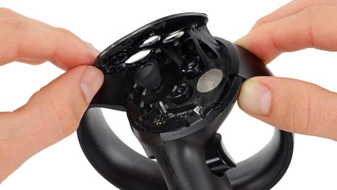
Photo courtesy iFixit (BY-NC-SA)
After top cover removal remove this single torx screw only, its deep in there and long, this holds the cover over the haptic. Now pry off the haptic grip cover.
Once the cover is off, you can see the haptic with a red and black wire going to it. The haptic is covered with kapton tape (yellow). First carefully remove the wires from the haptic, I snip them at the base of the LOSC/haptic after pulling up the kapton. Then very patiently and slowly and carefully pry out the haptic block. You might be able to just leave it in there but I saw no need.
The wire used is something like this from ebay for a few bucks. Hope you like soldering tinny coax wire!
Pigtail Antenna Cable RF0.81 IPEX to IPEX Connector Extension Cable 15cm Long
From here I soldered the 2 wires to a 0.8mm Diameter coaxial cable just in case I might encounter interference to any bluetooth RF or anything else with a twisted pair. I routed the wire up as per the red path here careful to avoid LED's, and capacitive sensors. Then drilled a small hole out the case next to the LED ring and Liquid electrical taped the wire to the edge of the ring to secure it and a few key points inside away from any electronics, to secure it. Ensure the grip button on the side doesn't smash the wire where it bends around to enter the top plate region.
Drill a hole in the plastic cup then line up and drill a corresponding hole in the mating cup. Or do as I did and line it up to one of the finger recess points on the perimeter. I used a brass tube for reflectivity and liquid electrical taped that tube in place. When using glue or liquid electrical tape on the cups either for magnet mounting or led or whatever, be sure to use something like a solid sheet of packaging tape between the cups to prevent gluing them together. Remove the tape 12-24 hrs once the glue has set.
Once the wire is secured carefully fit test each panel as you put it back ensuring the touch controller goes back together without interference.
Now the pictures start to get uglier.
Since Im using a top mount Mamut magnet cup I rout the wire over the top and secure it with liquid electrical tape. The end of the wire gets soldered to a white superbright LED V=3-3.4V. (note earlier how I said it must turn on at 3V and draw about 10mA. be sure of this before soldering that on or you will regret it. Test it in a game to be sure it lights up on a haptic pulse like firing a pistol or rifle.
In the above picture Red is the LED and photodiode. Green is the extra magnet I installed to improve pull away sheer force as I pull the stock into my shoulder. And blue is the epoxy putty I used to brace the mamut more directly to the touch handle so the LED ring was supporting less weight.
A bit of epoxy putty also helps at the base of the mamut mount to remove stress from the LED ring and smooth what the index finger feels when you have a 5 lb stock weighing down on your hand. I felt the need to round off the bottom of the mamut a lot so it didn't dig into my finger.
Part 1: Intro and disclaimer
Part 2: Trigger and grip mod:
Part 3: Fore grip Mod:
Part 4: Modifying the Haptic for a signal
Part 5: Pneumatic Recoil parts and Fire Control Circuit
Part 6: Scent Module
Photos courtesy iFixit (BY-NC-SA)
Now get a thin firm piece of plastic, like a fake credit card trash you get in the mail, sharpen one edge and carefully wedge it around the perimeter of the top plate but only going in about 2 mm so you dont damage anything. Carefully work it around to pry up the top plate.
Photo courtesy iFixit (BY-NC-SA)
After top cover removal remove this single torx screw only, its deep in there and long, this holds the cover over the haptic. Now pry off the haptic grip cover.
Once the cover is off, you can see the haptic with a red and black wire going to it. The haptic is covered with kapton tape (yellow). First carefully remove the wires from the haptic, I snip them at the base of the LOSC/haptic after pulling up the kapton. Then very patiently and slowly and carefully pry out the haptic block. You might be able to just leave it in there but I saw no need.
The wire used is something like this from ebay for a few bucks. Hope you like soldering tinny coax wire!
Pigtail Antenna Cable RF0.81 IPEX to IPEX Connector Extension Cable 15cm Long
From here I soldered the 2 wires to a 0.8mm Diameter coaxial cable just in case I might encounter interference to any bluetooth RF or anything else with a twisted pair. I routed the wire up as per the red path here careful to avoid LED's, and capacitive sensors. Then drilled a small hole out the case next to the LED ring and Liquid electrical taped the wire to the edge of the ring to secure it and a few key points inside away from any electronics, to secure it. Ensure the grip button on the side doesn't smash the wire where it bends around to enter the top plate region.
Drill a hole in the plastic cup then line up and drill a corresponding hole in the mating cup. Or do as I did and line it up to one of the finger recess points on the perimeter. I used a brass tube for reflectivity and liquid electrical taped that tube in place. When using glue or liquid electrical tape on the cups either for magnet mounting or led or whatever, be sure to use something like a solid sheet of packaging tape between the cups to prevent gluing them together. Remove the tape 12-24 hrs once the glue has set.
Once the wire is secured carefully fit test each panel as you put it back ensuring the touch controller goes back together without interference.
Now the pictures start to get uglier.
Since Im using a top mount Mamut magnet cup I rout the wire over the top and secure it with liquid electrical tape. The end of the wire gets soldered to a white superbright LED V=3-3.4V. (note earlier how I said it must turn on at 3V and draw about 10mA. be sure of this before soldering that on or you will regret it. Test it in a game to be sure it lights up on a haptic pulse like firing a pistol or rifle.
In the above picture Red is the LED and photodiode. Green is the extra magnet I installed to improve pull away sheer force as I pull the stock into my shoulder. And blue is the epoxy putty I used to brace the mamut more directly to the touch handle so the LED ring was supporting less weight.
A bit of epoxy putty also helps at the base of the mamut mount to remove stress from the LED ring and smooth what the index finger feels when you have a 5 lb stock weighing down on your hand. I felt the need to round off the bottom of the mamut a lot so it didn't dig into my finger.
Now, if you did it right every time the haptic should fire for a "shot fired" signal you should get a pulse of light out of the LED. the optical relay if done right is incredibly reliable. The sensing circuit later will have a POT to adjust the sensitivity.
But, while we are here there is one last modification.
To help ensure the recoil device doesn't fire when your not actually shooting, or braced with both controllers, we put an interrupt switch in the front cup. This switch takes almost no pressure to activate and is carefully scewed into the hole we drilled to stick up just enough for the cup to close the switch when the cup is engaged with a controller. This way you have to have both controllers in to have any chance of the recoil device firing. Thus room lights should be even less likely to set it off, and shooting one handed wont set it off and risk the recoil knocking the magnet cup free. I also put a bit of JB weld on the tip of the button so its harder and lower friction so it doesn't snag. I liquid electrical taped the back of the switch as a rubber impact absorber. Try not to impact it.
Part 1: Intro and disclaimer
Part 2: Trigger and grip mod:
Part 3: Fore grip Mod:
Part 4: Modifying the Haptic for a signal
Part 5: Pneumatic Recoil parts and Fire Control Circuit
Part 6: Scent Module
VR Pneumatic Recoil Rifle Stock: DIY Part 3: Simple Foregrip
Fore grip/hand guard-------------------------------
Im not a fan of VFG's for a variety of reasons and prefer to grab the handguard. Therefore, molding a pistol grip on to the controller for what is typically my supporting hand didn't make sense. Further, I whatever I put on it shouldn't be too unwieldy as a pistol grip for when I'm using the hand for the sidearm in a pinch. But long story short, the controller grips are too thin, a simple 1 3/4 to 2" OD pvc section 4 inches or so long, milled or drilled with some slots to simulate a keymod handguard, cut out button slots and we have a workable very cheap and simple solution. Plane the surfaces to a quasi octagon and you have a nice slip over handguard analog for the fore grip. Squeeze hard to temporarily deform it to be ovular for insertion/extraction and the battery cover is easy to get to. no glue needed. The spring force clamps the controller grip nicely and gives you a larger firmer grip to prevent hand cramp and help with your grip related propreoception for the supporting hand.
Part 1: Intro and disclaimer
Part 2: Trigger and grip mod:
Part 3: Fore grip Mod:
Part 4: Modifying the Haptic for a signal
Part 5: Pneumatic Recoil parts and Fire Control Circuit
Part 6: Scent Module
Sunday, March 3, 2019
VR Pneumatic Recoil Rifle Stock: DIY Part 2: Trigger Mod
Trigger Pull/Trigger Guard: -----------------------------------
Seriously even an airsoft GBBR has trigger pull of half a pound or more, at least for the better ones. The Oculus has a trigger pull of about 1 Oz This I had to fix and the fix is fairly simple. First you cant replace the spring easily as its hard to get to, and you may damage a flex cable, so leave the internals of the trigger on the touch controller alone.
With this mod, you can no longer just slap the 1oz trigger, you have to carefully squeeze and use better trigger discipline.
A 3d printed frame that clamps or mounts to the front of the controller giving a fake trigger that you pull which releases with more force and more crisply is fairly cheap and easy to implement and doesn't necessarily have to change the base controller at all. With the right clamp on or wrap around design it seemlessly converts your shooting hand to one that learns a bit better trigger discipline. And please remember to always keep your finger off of that trigger until your ready to pull the trigger on a valid target, even in VR! Thats what the trigger guard is for! *sigh... seen a few buddies get shot by some idiot screwing with their rifle stock in VR at the start of a match*
Glue trigger magnet in, wipe excess away, leave a bit on the end to prevent impact damage to the magnet.
Use your phone to align the assembly to the Oculus touch to minimally occlude the LED's.
lightly sand all interface surfaces then apply a thin layer of JB weld. Tape over any moving parts or parts you dont want epoxy getting on to so you can later remove the tape and extra glue.
Let it Dry overnight 12-24 hrs and your ready to rock n roll. Adjust pull weight by slipping thin layers of electrical tape between magnets. This also dampens the impact and reduces VR gun bounce due to impulse. Use a food scale to adjust to about 1lb breaking force.
Then remove all tape and install a stack of electrical tape about 1cm long by tape width, by 8-12 layers thick between the trigger and the Oculus trigger. Install a single layer of scotch tape over the electrical tape for friction reduction. This will allow you to dampen the impact on the trigger and use the shape of the metal trigger to force the Oculus trigger to travel much faster when the trigger breaks free thereby converting a short sharp pull to the long pull of the Oculus trigger. Alternatively stack 12 or more layers to pre-compress the Oculus trigger to just under the point where the VR gun fires to get a nice quick acting trigger as soon as the magnet breaks free. You may need to adjust the tape stack position higher or lower along the trigger to get it to break at the right point and take advantage of the lever action of the trigger mating shape.
A bit of green epoxy putty helps brace the trigger guard to the Mamut mount to help transfer stress and load bearing up into the stock without stressing the ring on the touch controller too much.
Finally, if you choose to cut up a cheap airsoft pistol grip and install it over the controller. Use a respirator and vaccuum before cutting and dremmeling out the inside as many are glass filled nylon. Cut it down the center, then trace patterns for the button and form fit. Then dremmel out the inside to mold around the controller. Tape sections of the controller with scotch tape to prevent gluing the controller shut, then very carefully glue the halves onto the controller. Take special note to protect buttons from glue. Also take extra special note that the side with the battery cover is taped entirely around the battery cover so glue only dries to the cover which slides off. Perhaps we can get someone like Mamut to make overmold pistol, 1911, glock, handguard grips.... Hint hint.
You can order parts for the trigger here, or go design your own.
Need one trigger and one frame to make an assembly.
https://www.shapeways.com/product/ZM2EZ4X2C/trigger-oculus-magnet-lh-stl
https://www.shapeways.com/product/GV7KEAPHW/tri-oc-mag-rh-base-stl
https://www.shapeways.com/product/4QYLXZEJ7/trigger-oculus-magnet-trigger-metal-l-or-r
Part 1: Intro and disclaimer
Part 2: Trigger and grip mod:
Part 3: Fore grip Mod:
Part 4: Modifying the Haptic for a signal
Part 5: Pneumatic Recoil parts and Fire Control Circuit
Part 6: Scent Module
Seriously even an airsoft GBBR has trigger pull of half a pound or more, at least for the better ones. The Oculus has a trigger pull of about 1 Oz This I had to fix and the fix is fairly simple. First you cant replace the spring easily as its hard to get to, and you may damage a flex cable, so leave the internals of the trigger on the touch controller alone.
With this mod, you can no longer just slap the 1oz trigger, you have to carefully squeeze and use better trigger discipline.
A 3d printed frame that clamps or mounts to the front of the controller giving a fake trigger that you pull which releases with more force and more crisply is fairly cheap and easy to implement and doesn't necessarily have to change the base controller at all. With the right clamp on or wrap around design it seemlessly converts your shooting hand to one that learns a bit better trigger discipline. And please remember to always keep your finger off of that trigger until your ready to pull the trigger on a valid target, even in VR! Thats what the trigger guard is for! *sigh... seen a few buddies get shot by some idiot screwing with their rifle stock in VR at the start of a match*
You will want to drill out the 3d print's trigger pivot hole to 1/8" and the magnet for the trigger pull force to about 4.6-4.7mm for a press fit. Do not glue either!
Glue trigger magnet in, wipe excess away, leave a bit on the end to prevent impact damage to the magnet.
A completed assembly ready for installation.
Use your phone to align the assembly to the Oculus touch to minimally occlude the LED's.
lightly sand all interface surfaces then apply a thin layer of JB weld. Tape over any moving parts or parts you dont want epoxy getting on to so you can later remove the tape and extra glue.
Let it Dry overnight 12-24 hrs and your ready to rock n roll. Adjust pull weight by slipping thin layers of electrical tape between magnets. This also dampens the impact and reduces VR gun bounce due to impulse. Use a food scale to adjust to about 1lb breaking force.
Then remove all tape and install a stack of electrical tape about 1cm long by tape width, by 8-12 layers thick between the trigger and the Oculus trigger. Install a single layer of scotch tape over the electrical tape for friction reduction. This will allow you to dampen the impact on the trigger and use the shape of the metal trigger to force the Oculus trigger to travel much faster when the trigger breaks free thereby converting a short sharp pull to the long pull of the Oculus trigger. Alternatively stack 12 or more layers to pre-compress the Oculus trigger to just under the point where the VR gun fires to get a nice quick acting trigger as soon as the magnet breaks free. You may need to adjust the tape stack position higher or lower along the trigger to get it to break at the right point and take advantage of the lever action of the trigger mating shape.
A bit of green epoxy putty helps brace the trigger guard to the Mamut mount to help transfer stress and load bearing up into the stock without stressing the ring on the touch controller too much.
Finally, if you choose to cut up a cheap airsoft pistol grip and install it over the controller. Use a respirator and vaccuum before cutting and dremmeling out the inside as many are glass filled nylon. Cut it down the center, then trace patterns for the button and form fit. Then dremmel out the inside to mold around the controller. Tape sections of the controller with scotch tape to prevent gluing the controller shut, then very carefully glue the halves onto the controller. Take special note to protect buttons from glue. Also take extra special note that the side with the battery cover is taped entirely around the battery cover so glue only dries to the cover which slides off. Perhaps we can get someone like Mamut to make overmold pistol, 1911, glock, handguard grips.... Hint hint.
You can order parts for the trigger here, or go design your own.
Need one trigger and one frame to make an assembly.
https://www.shapeways.com/product/ZM2EZ4X2C/trigger-oculus-magnet-lh-stl
https://www.shapeways.com/product/GV7KEAPHW/tri-oc-mag-rh-base-stl
https://www.shapeways.com/product/4QYLXZEJ7/trigger-oculus-magnet-trigger-metal-l-or-r
Part 1: Intro and disclaimer
Part 2: Trigger and grip mod:
Part 3: Fore grip Mod:
Part 4: Modifying the Haptic for a signal
Part 5: Pneumatic Recoil parts and Fire Control Circuit
Part 6: Scent Module
VR Pneumatic Recoil Rifle Stock: DIY PART 1: Intro
Ok so a few months ago I got a VR headset, then found Onward among other games like contractors and Arizona sunshine. Great fun, Pretty good weapon handling. But.... still missing things. One of the biggest was the feel of the rifles wasn't right. Rants aside about vertical fore grips the next aspects of the virtual rifles that annoyed me was the lack of recoil or incredibly weak trigger pull. Anyway, why should you read this absurdly long post. It tells how to make the following pneumatic recoil stock for VR games for crazy DIY'ers who want a forcetube, but want more than 60N force and they want it right now!'ish. To be upgraded with a forcetube fire control board once their kickstarter is over. Go support it!
DISCLAIMER: Use at your own risk. You assume all responsibility for any injury or property damage incurred. I include this for informational purposes only and what you do with this information is on you. If you lack sufficient expertise to vet the information before trying to replicate it you are highly likely to cause injury or death to yourself or others near you. Don't burn your house down, don't smash your fingers in it, don't get blind by shrapnel, or deafened by the concussion or air venting, always wear safety goggles, hearing protection or any other PPE that may be advisable. Have a fire extinguisher on hand, and someone who checks in on you. Don't electrocute yourself be careful of lipos or other high density energy sources as they can explode or cause fire if you don't know what your doing, don't puncture them etc etc. Don't try this at home even though I did. And if you do always start at low power with the test apparatus far from you and or a safety barrier between you and anything that may fly off of it directly or indirectly. You've been warned. The forces being used here are dangerous. Any person consultations are theoretical and you are to use your own judgement as to whether or not you follow any advice. If you are not an adult stop reading this and go ask a responsible adult for guidance.
EDIT: Note do not use LiIon batteries. The stock kicks too hard and after 10k rounds or so compacts the foil in the batteries. Use a tethered 12V supply parallel to the airline or NiCd NiMH or other batteries proven to take a beating with radio controlled vehicles. (dont use LiPos without great dampening)
Part 1: Intro and disclaimer
Part 2: Trigger and grip mod:
Part 3: Fore grip Mod:
Part 4: Modifying the Haptic for a signal
Part 5: Pneumatic Recoil parts and Fire Control Circuit
Part 6: Scent Module
But, First lets discuss what felt recoil is.
Actually before that, Why not just go buy a stock from someone who makes VR rifles. Well they usually dont incorperate hand controllers so the game has no idea what your hand is doing if you take it away from the rifle. And for immersion that one is pretty big to me. Plus ego says I want to build it. Ok back to felt recoil.
Lets leave the bulk of it to someone else to discuss who should know what they are talking about. Searching the web this guy seemed to take a decent examination of it so Ill make him the gold standard out of laziness and not knowing better myself.
https://precisionrifleblog.com/2015/07/01/muzzle-brakes-recoil-primer-test-equipment-rifles/
But just in case they ever take it down, Im reposting a few of their images below.
Self explanatory, lots of energy produced and if I recall the rough rule of thumb is not much more than 1/3 of the energy goes into the bullet and we can crudely just say the momentum of the rifle at the end equals the momentum of the bullet and at worse we are off by a factor of 2x. And we are playing video games so I can stomach 2x easily.
Now for most games I imagine I would want something between a 22lr (very weak recoil) in an unforgiving wood stock and a 223 round (roughly equivalent to 556) with a direct impingement AR style bolt. Maybe later we want to "upgrade" to perceived recoil of a larger cartridge in a solid wood stock (ouch).
As his article states there is argument over what is the closest measurand of perceived recoil but again I want ballpark cuz its a game and the controllers can't take a hard recoil.
But I can work with total energy, Or impulse or whatever. Its basic math and we are spitballing.
The thing is many of these curves measure in the hundred of newtons or footpounds in fractions of a second... so yea, spitballing.
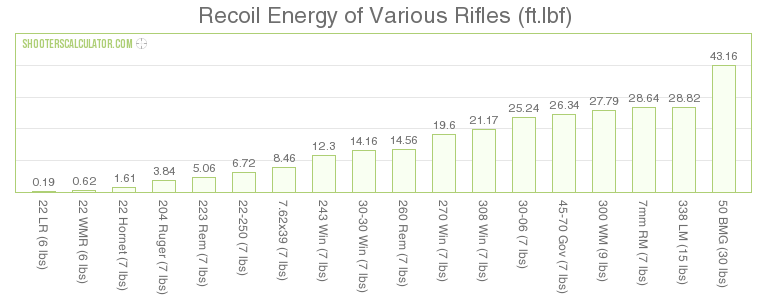
More searching found a table of rough energies.
So if life were ideal we would have between 0.2 and 5 ft-LbF or about 0.3 to 7 joules.
Now measuring the area under the curve or roughly force times time gives impulse, or change in momentum per unit time.
ForceTube Recoil:============================
So to get really sloppy with math lets look at forcetube. (correct me if I have any of this wrong)
What we know of their prototypes (the production should be more powerful)
Theirs works by applying a near continuous force from the transducers to the buttpad insert over a distance of 5mm. It is direct force to the shoulder counter balanced by your pull of the stock into your shoulder.
F~ 60N Force of the solenoid/spring
M~ 2.5kg weight of entire stock and controllers.
dx ~ 5mm Max displacement of the shoulder insert or *2 for total return per cycle
dt ~ 50ms Lets assume they can get up to 20 rounds per second to simulate nearly all full auto.
Lets calculate a few different ways to get a rough envelope to account for estimate errors.
Energy / work
F * dx = 60*.005=0.3 Nm ---this came to the highest so Ill just assume this value as the max raw energy.
1/2 M * V^2 = 0.5 * 2.5 * (.01/.05)^2 = .05 Nm --it assumes accelerating the entire stock using the velocity of the insert and assuming the same velocity of the stock... a bad assumption yes.
Impulse --I dont have a chart above but may be useful to compare later.
F*dt = 60 * .05 = 3 Ns --- again we will take this one as the highest
M*dV = 10mm/50ms*2.5kg = 0.01/.05*2.5=0.5 kg m/s
DISCLAIMER: Use at your own risk. You assume all responsibility for any injury or property damage incurred. I include this for informational purposes only and what you do with this information is on you. If you lack sufficient expertise to vet the information before trying to replicate it you are highly likely to cause injury or death to yourself or others near you. Don't burn your house down, don't smash your fingers in it, don't get blind by shrapnel, or deafened by the concussion or air venting, always wear safety goggles, hearing protection or any other PPE that may be advisable. Have a fire extinguisher on hand, and someone who checks in on you. Don't electrocute yourself be careful of lipos or other high density energy sources as they can explode or cause fire if you don't know what your doing, don't puncture them etc etc. Don't try this at home even though I did. And if you do always start at low power with the test apparatus far from you and or a safety barrier between you and anything that may fly off of it directly or indirectly. You've been warned. The forces being used here are dangerous. Any person consultations are theoretical and you are to use your own judgement as to whether or not you follow any advice. If you are not an adult stop reading this and go ask a responsible adult for guidance.
EDIT: Note do not use LiIon batteries. The stock kicks too hard and after 10k rounds or so compacts the foil in the batteries. Use a tethered 12V supply parallel to the airline or NiCd NiMH or other batteries proven to take a beating with radio controlled vehicles. (dont use LiPos without great dampening)
Part 1: Intro and disclaimer
Part 2: Trigger and grip mod:
Part 3: Fore grip Mod:
Part 4: Modifying the Haptic for a signal
Part 5: Pneumatic Recoil parts and Fire Control Circuit
Part 6: Scent Module
But, First lets discuss what felt recoil is.
Actually before that, Why not just go buy a stock from someone who makes VR rifles. Well they usually dont incorperate hand controllers so the game has no idea what your hand is doing if you take it away from the rifle. And for immersion that one is pretty big to me. Plus ego says I want to build it. Ok back to felt recoil.
Lets leave the bulk of it to someone else to discuss who should know what they are talking about. Searching the web this guy seemed to take a decent examination of it so Ill make him the gold standard out of laziness and not knowing better myself.
https://precisionrifleblog.com/2015/07/01/muzzle-brakes-recoil-primer-test-equipment-rifles/
But just in case they ever take it down, Im reposting a few of their images below.
Self explanatory, lots of energy produced and if I recall the rough rule of thumb is not much more than 1/3 of the energy goes into the bullet and we can crudely just say the momentum of the rifle at the end equals the momentum of the bullet and at worse we are off by a factor of 2x. And we are playing video games so I can stomach 2x easily.
Now for most games I imagine I would want something between a 22lr (very weak recoil) in an unforgiving wood stock and a 223 round (roughly equivalent to 556) with a direct impingement AR style bolt. Maybe later we want to "upgrade" to perceived recoil of a larger cartridge in a solid wood stock (ouch).
As his article states there is argument over what is the closest measurand of perceived recoil but again I want ballpark cuz its a game and the controllers can't take a hard recoil.
But I can work with total energy, Or impulse or whatever. Its basic math and we are spitballing.
The thing is many of these curves measure in the hundred of newtons or footpounds in fractions of a second... so yea, spitballing.
More searching found a table of rough energies.
So if life were ideal we would have between 0.2 and 5 ft-LbF or about 0.3 to 7 joules.
Now measuring the area under the curve or roughly force times time gives impulse, or change in momentum per unit time.
ForceTube Recoil:============================
So to get really sloppy with math lets look at forcetube. (correct me if I have any of this wrong)
What we know of their prototypes (the production should be more powerful)
Theirs works by applying a near continuous force from the transducers to the buttpad insert over a distance of 5mm. It is direct force to the shoulder counter balanced by your pull of the stock into your shoulder.
F~ 60N Force of the solenoid/spring
M~ 2.5kg weight of entire stock and controllers.
dx ~ 5mm Max displacement of the shoulder insert or *2 for total return per cycle
dt ~ 50ms Lets assume they can get up to 20 rounds per second to simulate nearly all full auto.
Lets calculate a few different ways to get a rough envelope to account for estimate errors.
Energy / work
F * dx = 60*.005=0.3 Nm ---this came to the highest so Ill just assume this value as the max raw energy.
1/2 M * V^2 = 0.5 * 2.5 * (.01/.05)^2 = .05 Nm --it assumes accelerating the entire stock using the velocity of the insert and assuming the same velocity of the stock... a bad assumption yes.
Impulse --I dont have a chart above but may be useful to compare later.
F*dt = 60 * .05 = 3 Ns --- again we will take this one as the highest
M*dV = 10mm/50ms*2.5kg = 0.01/.05*2.5=0.5 kg m/s
To compare to the chart above .3Nm converts to 0.22 ft Lbf so about that of a 22lr!
or at worst .05Nm => 1/6th that of a 22lr
Pneumatic Recoil:===========================
The pneumatic recoil, as its presently designed, accelerates an 8oz mass at 60psi to slam into a glass filled nylon and firm rubber butpad (1cm thick in total) directly into the shoulder. So rather than a solid force you feel a shock or more of an momentum transfer. I chose 8oz as that is the weight of a light AR15 bolt according to google.
Ok the specs on my parts are.
Pressure 60Psi peak
Piston diameter 1 1/16" website says for 60PSI it delivers about 50lbf
F = 50lbf or 222N
Mass of bounce weight 8 oz (1/2 lb) or 0.227kg
Mass of stock with everything 5.5lbs or 2.5kg
dx 2" throw per direction or 50mm
dt ~ 70ms for forward and return round trip
Energy / work
F*dx = 222N * .05m = 11Nm
1/2 M * V^2 = 0.5 * 0.227 * (.1/.07)^2 = 0.23Nm
So at most, assuming the pneumatic actually delivered max pressure over the entire stroke the total energy would be on par with 8.1ftlbf or about an AK or as little as 0.17ftlbf or 90% of a 22lr at worse.
Now looking at raw energy especially since these work by different mechanisms its difficult to actually compare them. without having both on the same load cell with the same reference mass.
But one upgrade I may implement soon is a sliding butt plate that the mass impacts directly and it slides freely of the stock so then all of the momentum does transfer directly to the shoulder, and for the past few mm you get a full 200+ newtons of force. This will take some careful design to ensure it doesn't shatter or get bound.
Subscribe to:
Posts (Atom)