
Ok for this, I didnt take very good pictures during my hack so Im going to borrow very liberally from https://www.roadtovr.com/oculus-touch-teardown-disassembly/
and from https://www.ifixit.com/Teardown/Oculus+Touch+Teardown/75109
Also, in retrospect this modification should be done BEFORE part 2 unless your just going to wait for the forcetube kickstarter for the signal board.
Most of the pictures initially are from them.
However partway through we stop because they take it apart too far for our needs. There are only 4 screws you need to takeout (maybe 5)
 Remove the battery cover and battery. Remove the decal. Use a torx screwdriver to remove the screws. I believe 3 are visible at this point. Keep track of lengths and where they go (note taking is a good idea).
Photos courtesy iFixit (BY-NC-SA)

Now get a thin firm piece of plastic, like a fake credit card trash you get in the mail, sharpen one edge and carefully wedge it around the perimeter of the top plate but only going in about 2 mm so you dont damage anything. Carefully work it around to pry up the top plate.
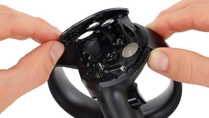
Photo courtesy iFixit (BY-NC-SA)
After top cover removal remove this single torx screw only, its deep in there and long, this holds the cover over the haptic. Now pry off the haptic grip cover.

Once the cover is off, you can see the haptic with a red and black wire going to it. The haptic is covered with kapton tape (yellow). First carefully remove the wires from the haptic, I snip them at the base of the LOSC/haptic after pulling up the kapton. Then very patiently and slowly and carefully pry out the haptic block. You might be able to just leave it in there but I saw no need.
 The wire used is something like this from ebay for a few bucks. Hope you like soldering tinny coax wire!
Pigtail Antenna Cable RF0.81 IPEX to IPEX Connector Extension Cable 15cm Long
From here I soldered the 2 wires to a 0.8mm Diameter coaxial cable just in case I might encounter interference to any bluetooth RF or anything else with a twisted pair. I routed the wire up as per the red path here careful to avoid LED's, and capacitive sensors. Then drilled a small hole out the case next to the LED ring and Liquid electrical taped the wire to the edge of the ring to secure it and a few key points inside away from any electronics, to secure it. Ensure the grip button on the side doesn't smash the wire where it bends around to enter the top plate region.
Drill a hole in the plastic cup then line up and drill a corresponding hole in the mating cup. Or do as I did and line it up to one of the finger recess points on the perimeter. I used a brass tube for reflectivity and liquid electrical taped that tube in place. When using glue or liquid electrical tape on the cups either for magnet mounting or led or whatever, be sure to use something like a solid sheet of packaging tape between the cups to prevent gluing them together. Remove the tape 12-24 hrs once the glue has set.
Once the wire is secured carefully fit test each panel as you put it back ensuring the touch controller goes back together without interference.
Now the pictures start to get uglier.
Since Im using a top mount Mamut magnet cup I rout the wire over the top and secure it with liquid electrical tape. The end of the wire gets soldered to a white superbright LED V=3-3.4V. (note earlier how I said it must turn on at 3V and draw about 10mA. be sure of this before soldering that on or you will regret it. Test it in a game to be sure it lights up on a haptic pulse like firing a pistol or rifle.


In the above picture Red is the LED and photodiode. Green is the extra magnet I installed to improve pull away sheer force as I pull the stock into my shoulder. And blue is the epoxy putty I used to brace the mamut more directly to the touch handle so the LED ring was supporting less weight.
A bit of epoxy putty also helps at the base of the mamut mount to remove stress from the LED ring and smooth what the index finger feels when you have a 5 lb stock weighing down on your hand. I felt the need to round off the bottom of the mamut a lot so it didn't dig into my finger.

Now, if you did it right every time the haptic should fire for a "shot fired" signal you should get a pulse of light out of the LED. the optical relay if done right is incredibly reliable. The sensing circuit later will have a POT to adjust the sensitivity.
But, while we are here there is one last modification.
To help ensure the recoil device doesn't fire when your not actually shooting, or braced with both controllers, we put an interrupt switch in the front cup. This switch takes almost no pressure to activate and is carefully scewed into the hole we drilled to stick up just enough for the cup to close the switch when the cup is engaged with a controller. This way you have to have both controllers in to have any chance of the recoil device firing. Thus room lights should be even less likely to set it off, and shooting one handed wont set it off and risk the recoil knocking the magnet cup free. I also put a bit of JB weld on the tip of the button so its harder and lower friction so it doesn't snag. I liquid electrical taped the back of the switch as a rubber impact absorber. Try not to impact it.

Part 1: Intro and disclaimer
Part 2: Trigger and grip mod:
Part 3: Fore grip Mod:
Part 4: Modifying the Haptic for a signal
Part 5: Pneumatic Recoil parts and Fire Control Circuit
Part 6: Scent Module
No comments:
Post a Comment